
When working with digital buses like CAN, subtle wiring details can make or break reliability. Over long data lines, reflections creep in if impedance and termination aren’t handled correctly. These reflections distort the signal and can lead to unpredictable errors—something I’ve seen cause real headaches in robotics projects.
To show this effect, we recently ran a series of signal integrity tests using our Cyder pre-made CAN cabling and then extended the experiment to intentionally non-ideal wiring. The results highlight why termination resistors, cable geometry, and even device transceiver rise times all matter.
Test Setup
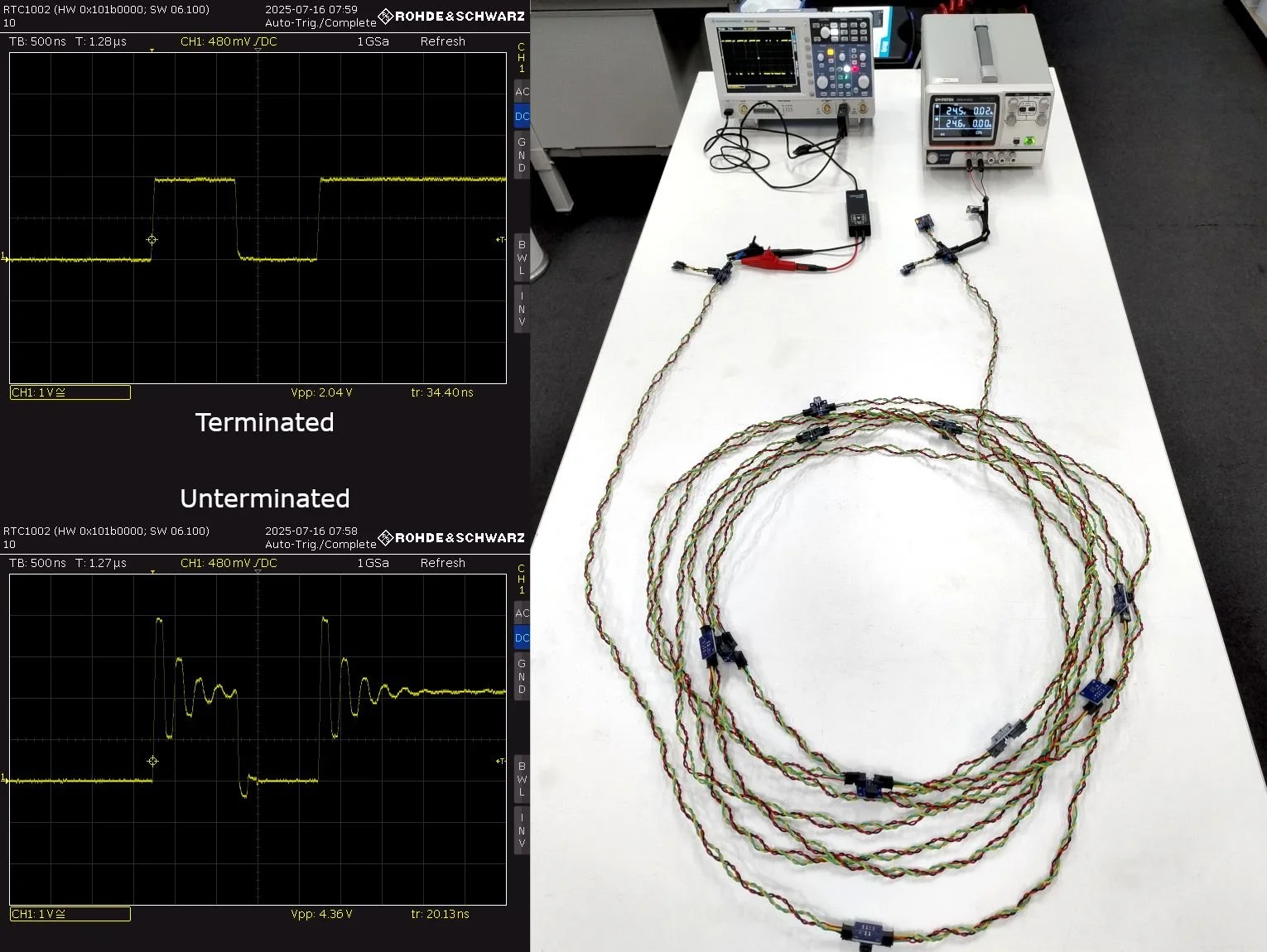
To evaluate signal integrity, we constructed a 10 m CAN bus from ten 1 m Cyder cables linked with Cyder data taps. A Cyder IMU module transmitted 1 Mbps CAN traffic from one end, while an oscilloscope with a differential probe measured the signal at the other end.
Key parameters included:
Signal velocity: ~150 mm/ns in copper wire
Transceiver rise time: ~34 ns (~5.1 m equivalent propagation length)
Bus length: 10 m, sufficient to exhibit transmission line effects
Results: Termination vs. No Termination
With correct 120 Ω termination, the waveform was clean and stable, swinging between 0 V and 2 V without distortion.
When the termination was removed, however, strong reflections appeared. Oscillations pushed peak voltages to 4.36 V. While not damaging to hardware, such reflections can easily cause data corruption—especially problematic in robotics systems that demand consistent, error-free communication.
Untwisted Wires: What Happens Without Controlled Impedance
To investigate uncontrolled impedance, we repeated the test using 10 m of untwisted hookup wire. In this configuration, impedance was both higher and inconsistent along the line:
With termination: The line was effectively over-terminated. The signal reflected multiple times before reaching its final voltage level.
Without termination: Reflections dominated the waveform to the point where the true signal was difficult to distinguish.
This illustrates why twisted differential pairs—and careful impedance matching—are not optional in high-speed data systems.

What About Stubs?
Another common consideration is stub length. How long can a branch line be before it compromises the bus?
We tested two cases:
Multiple 1 m stubs attached to the main bus
A single 5 m stub mid-bus
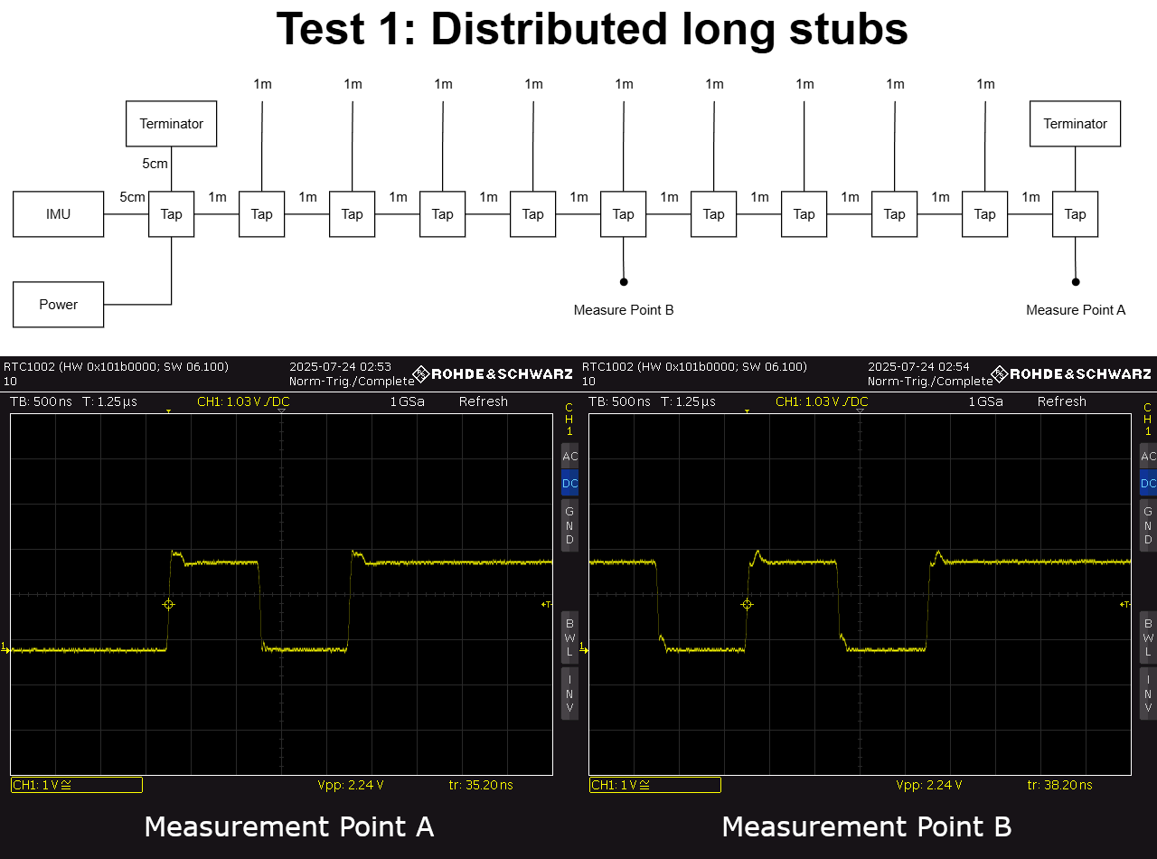

Both scenarios introduced some ringing, yet the bus remained functional and signals were still interpretable. However, this margin of tolerance depends strongly on the rise time of the transceivers.
Our CAN devices use relatively slow drivers (~32 ns rise time), which helps dampen reflections. In contrast, older or faster devices with rise times as short as 1 ns can make even short stubs highly problematic. This means what works in one setup may fail in another. As a rule, stub lengths should always be minimized for predictable performance.
Key Takeaways
Always terminate correctly. A simple missing resistor can destabilize the whole bus.
Terminate correctly. Proper termination prevents damaging reflections and ensures data integrity.
Control impedance. Twisted differential pairs maintain consistency and signal quality.
Consider rise time. Faster transceivers are less forgiving and magnify the impact of poor layout.
Minimize stubs. Even when a system “works,” long or numerous stubs can erode reliability.
At Cyborg Dynamics Engineering, we design Cyder products to simplify these challenges for robotics developers. By using pre-engineered cables, interconnects, and termination solutions, teams can avoid subtle signal integrity issues and focus on building their applications with confidence.